ADT 2007 New Feature Focus - Automating AEC Dimensions
In an earlier post, I spotlighted the improvements to AEC Dimensions as one of the big new features of ADT 2007. The improvements can be grouped under two main areas: flexibility and control.
While the flexibility aspect of AEC Dimensions is huge, I'm going to focus on the control side of things in this post. If you want to learn about the flexibility part, play with the grips and check out some of the stuff on the right click menu - it's pretty self-explanatory.
On the control and automation side, however, things aren't quite so obvious unless you do a little digging. Good news. I've already done it for you.
The biggest limitation with AEC Dimensions up until now has been that you could not pre-configure exactly which components (and which part of said components) were to be dimensioned in a wall and worse, you couldn't change things much once the dimension was placed. The flexibility of the new AEC Dimensions takes care of the second part, and the new controls take care of the first part.
The first thing you need to do is get your wall styles configured for AEC Dimensioning. When you create a component now you should specify what it's use is - structural or non-structural. You should also specify for each component whether it should be dimensioned or not, and which part of the component should be dimensioned (left side, right side, center or all three).
In the figure below, I've configured the brick veneer to be a candidate for dimensioning on the exterior side of the component. I've also configured the stud as a structural component and made it a candidate for dimensioning on the exterior side of the stud. Also, note at the bottom left corner of the dialog, you now can specify which is the exterior or interior side of the wall. By the way, you can specify both the positive (left) side of the wall and the negative (right) side as exterior or both as interior without ADT complaining, but I wouldn't recommend it unless you LIKE working with bi-polar data...

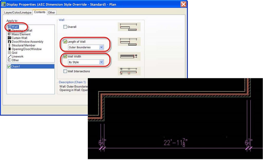
Once you've configured the wall style, you need to likewise configure the AEC Dimension style. For simplicity's sake, I'm going to work with a single chain dimension to focus specifically on our wall condition, but if you've worked with AEC Dimensions at all, you know you can have as many chains as you like, each one configured for different parameters.
In the Contents tab of my AEC Dimension style, I've configured the "Wall" dimensions to dimension the wall length to the outer boundaries. Most importantly, however, note in the figure below that I've configured the wall width to "By Style", and this causes the indicated result.

Using these simple controls (you might also want to experiment with different combinations of "Wall Length" and "Wall Width - By Style" and "Wall Width - By Structural Style", you can automate a large part of your AEC Dimensions while still maintaining the dimension standards that you prefer. In those instances where a non-standard condition appears, use the grips and the right click menu to remove extension lines, add extension lines and most importantly move extension lines, all the while maintaining the associativity of the dimensions, even across XREFs.
Ever since ADT R3 when AEC Dimensions were introduced, I've told my students that I didn't think they were usable for construction documents but that there was huge potential, and to keep an eye on them. Now, I feel that potential has finally been realized!
While the flexibility aspect of AEC Dimensions is huge, I'm going to focus on the control side of things in this post. If you want to learn about the flexibility part, play with the grips and check out some of the stuff on the right click menu - it's pretty self-explanatory.
On the control and automation side, however, things aren't quite so obvious unless you do a little digging. Good news. I've already done it for you.
The biggest limitation with AEC Dimensions up until now has been that you could not pre-configure exactly which components (and which part of said components) were to be dimensioned in a wall and worse, you couldn't change things much once the dimension was placed. The flexibility of the new AEC Dimensions takes care of the second part, and the new controls take care of the first part.
The first thing you need to do is get your wall styles configured for AEC Dimensioning. When you create a component now you should specify what it's use is - structural or non-structural. You should also specify for each component whether it should be dimensioned or not, and which part of the component should be dimensioned (left side, right side, center or all three).
In the figure below, I've configured the brick veneer to be a candidate for dimensioning on the exterior side of the component. I've also configured the stud as a structural component and made it a candidate for dimensioning on the exterior side of the stud. Also, note at the bottom left corner of the dialog, you now can specify which is the exterior or interior side of the wall. By the way, you can specify both the positive (left) side of the wall and the negative (right) side as exterior or both as interior without ADT complaining, but I wouldn't recommend it unless you LIKE working with bi-polar data...

Once you've configured the wall style, you need to likewise configure the AEC Dimension style. For simplicity's sake, I'm going to work with a single chain dimension to focus specifically on our wall condition, but if you've worked with AEC Dimensions at all, you know you can have as many chains as you like, each one configured for different parameters.
In the Contents tab of my AEC Dimension style, I've configured the "Wall" dimensions to dimension the wall length to the outer boundaries. Most importantly, however, note in the figure below that I've configured the wall width to "By Style", and this causes the indicated result.
Using these simple controls (you might also want to experiment with different combinations of "Wall Length" and "Wall Width - By Style" and "Wall Width - By Structural Style", you can automate a large part of your AEC Dimensions while still maintaining the dimension standards that you prefer. In those instances where a non-standard condition appears, use the grips and the right click menu to remove extension lines, add extension lines and most importantly move extension lines, all the while maintaining the associativity of the dimensions, even across XREFs.
Ever since ADT R3 when AEC Dimensions were introduced, I've told my students that I didn't think they were usable for construction documents but that there was huge potential, and to keep an eye on them. Now, I feel that potential has finally been realized!
posted by Matt Dillon at 7:57 PM
![]()


1 Comments:
Nice explaination Matt. I agree. ADT needed the ability to dimension to the wall core etc. A welcomed improvement that should allow users to take full advantage of AEC DIMs now.
Post a Comment
<< Home